
机器人学第六章作业
机器人学第六章作业
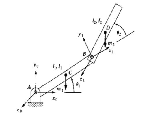
分别用 Lagrange 法和 Newton-Euler 法推导建立如图所示2自由度机器人的动力学方程。连杆质心位于连杆几何中心,其转动惯量分别为\(I_1\)和\(I_2\)。
Lagrange 法
以图1中\(O-X_0Y_0Z_0\)为极坐标系,连杆1的质心 \(C\) 的位置是: \[ \begin{cases} x_1=\frac{1}{2}l_1\cos \theta _1\\ y_1=\frac{1}{2}l_1\sin \theta _1\\ \end{cases} \] 对上式相对于时间 \(t\) 求导,可得质心 \(C\) 的速度是: \[ \begin{cases} \dot{x}_1=-\frac{1}{2}l_1\cos \theta _1\dot{\theta}_1\\ \dot{y}_1=\frac{1}{2}l_1\sin \theta _1\dot{\theta}_1\\ \end{cases} \] 连杆2的质心 \(D\) 的位置是: \[ \begin{cases} x_2=l_1\cos \theta _1+\frac{1}{2}l_2\cos \left( \theta _1+\theta _2 \right)\\ y_2=l_1\sin \theta _1+\frac{1}{2}l_2\sin \left( \theta _1+\theta _2 \right)\\ \end{cases} \] 对上式相对于时间 \(t\) 求导,可得质心 \(D\) 的速度是: \[ \begin{cases} \dot{x}_2=-l_1\sin \theta _1\dot{\theta}_1-\frac{1}{2}l_2\sin \left( \theta _1+\theta _2 \right) \cdot \left( \dot{\theta}_1+\dot{\theta}_2 \right)\\ \dot{y}_2=l_1\cos \theta _1\dot{\theta}_1+\frac{1}{2}l_2\cos \left( \theta _1+\theta _2 \right) \cdot \left( \dot{\theta}_1+\dot{\theta}_2 \right)\\ \end{cases} \] 连杆1的动能为: \[ E_{K1}=\frac{1}{2}m_1v_{1}^{2}=\frac{1}{2}m_1\left( \dot{x}_{1}^{2}+\dot{y}_{1}^{2} \right) =\frac{1}{4}m_1l_{1}^{2}\dot{\theta}_{1}^{2} \] 连杆2的动能为: \[ \begin{aligned} E_{K2}&=\frac{1}{2}m_2v_{2}^{2}=\frac{1}{2}m_2\left( \dot{x}_{2}^{2}+\dot{y}_{2}^{2} \right) \\&=\frac{1}{2}m_2l_{1}^{2}\dot{\theta}_{1}^{2}+\frac{1}{8}m_2l_{2}^{2}\left( \dot{\theta}_1+\dot{\theta}_2 \right) ^2+\frac{1}{2}m_2l_1l_2\cos \theta _2\cdot \left( \dot{\theta}_{1}^{2}+\dot{\theta}_1\dot{\theta}_2 \right) \end{aligned} \] 所以,机器人的总动能为: \[ \begin{aligned} E_K&=E_{K1}+E_{K2}\\&=\frac{1}{4}m_1l_{1}^{2}\dot{\theta}_{1}^{2}+\frac{1}{2}m_2l_{1}^{2}\dot{\theta}_{1}^{2}+\frac{1}{8}m_2l_{2}^{2}\left( \dot{\theta}_1+\dot{\theta}_2 \right) ^2+\frac{1}{2}m_2l_1l_2\cos \theta _2\cdot \left( \dot{\theta}_{1}^{2}+\dot{\theta}_1\dot{\theta}_2 \right) \end{aligned} \] 连杆1的势能为: \[ E_{P1}=m_1gl_1\sin \theta _1 \] 连杆2的势能为: \[ E_{P2}=m_2g\left( l_1\sin \theta _1+l_2\sin \theta _2 \right) \] 所以,机器人的总势能为: \[ E_P=E_{P1}+E_{P2}=m_1gl_1\sin \theta _1+m_2g\left( l_1\sin \theta _1+l_2\sin \theta _2 \right) \] 由Lagrange 动力学方程分别计算关节1和关节2的驱动力。
关节1上的驱动力为: \[ \begin{aligned} f_1&=\frac{\mathrm{d}}{\mathrm{d}t}\frac{\partial E_K}{\partial \dot{q}_1}-\frac{\partial E_K}{\partial q_1}+\frac{\partial E_P}{\partial q_1} \\ &=\frac{\mathrm{d}}{\mathrm{d}t}\frac{\partial E_K}{\partial \dot{\theta}_1}-\frac{\partial E_K}{\partial \theta _1}+\frac{\partial E_P}{\partial \theta _1} \\ &=\frac{\mathrm{d}}{\mathrm{d}t}\left( \frac{1}{2}m_1l_{1}^{2}\dot{\theta}_1+m_2l_{1}^{2}\dot{\theta}_1+\frac{1}{4}m_2l_{2}^{2}\dot{\theta}_1+\frac{1}{4}m_2l_{2}^{2}\dot{\theta}_2+m_2l_1l_2\cos \theta _2\dot{\theta}_1+\frac{1}{2}m_2l_1l_2\cos \theta _2\dot{\theta}_2 \right) \\&\quad\ -0+m_1gl_1\cos \theta _1\dot{\theta}_1+m_2gl_1\cos \theta _1\dot{\theta}_1 \\ &=\frac{1}{2}m_1l_{1}^{2}\ddot{\theta}_1+m_2l_{1}^{2}\ddot{\theta}_1+\frac{1}{4}m_2l_{2}^{2}\ddot{\theta}_1+\frac{1}{4}m_2l_{2}^{2}\ddot{\theta}_2-m_2l_1l_2\sin \theta _2\dot{\theta}_1\dot{\theta}_2+m_2l_1l_2\cos \theta _2\ddot{\theta}_1 \\&\quad\ +\frac{1}{2}m_2l_1l_2\sin \theta _2\dot{\theta}_{2}^{2}+\frac{1}{2}m_2l_1l_2\cos \theta _2\ddot{\theta}_2+m_1gl_1\cos \theta _1\dot{\theta}_1+m_2gl_1\cos \theta _1\dot{\theta}_1 \end{aligned} \] 关节1是转动关节,所以 \(f_1\) 是转矩,即 \[ \begin{aligned} \tau _1&=\frac{1}{2}m_1l_{1}^{2}\ddot{\theta}_1+m_2l_{1}^{2}\ddot{\theta}_1+\frac{1}{4}m_2l_{2}^{2}\ddot{\theta}_1+\frac{1}{4}m_2l_{2}^{2}\ddot{\theta}_2-m_2l_1l_2\sin \theta _2\dot{\theta}_1\dot{\theta}_2+m_2l_1l_2\cos \theta _2\ddot{\theta}_1\\&\quad\ +\frac{1}{2}m_2l_1l_2\sin \theta _2\dot{\theta}_{2}^{2}+\frac{1}{2}m_2l_1l_2\cos \theta _2\ddot{\theta}_2+m_1gl_1\cos \theta _1\dot{\theta}_1+m_2gl_1\cos \theta _1\dot{\theta}_1 \end{aligned} \] 关节2上的驱动力为: \[ \begin{aligned} f_2&=\frac{\mathrm{d}}{\mathrm{d}t}\frac{\partial E_K}{\partial \dot{q}_2}-\frac{\partial E_K}{\partial q_2}+\frac{\partial E_P}{\partial q_2} \\ &=\frac{\mathrm{d}}{\mathrm{d}t}\frac{\partial E_K}{\partial \dot{\theta}_2}-\frac{\partial E_K}{\partial \theta _2}+\frac{\partial E_P}{\partial \theta _2} \\ &=\frac{\mathrm{d}}{\mathrm{d}t}\left( \frac{1}{4}m_2l_{2}^{2}\dot{\theta}_2+\frac{1}{4}m_2l_{2}^{2}\dot{\theta}_1+\frac{1}{2}m_2l_1l_2\cos \theta _2\dot{\theta}_1 \right) \\&\quad\ +\frac{1}{2}m_2l_1l_2\sin \theta _2\left( \dot{\theta}_{1}^{2}\dot{\theta}_2+\dot{\theta}_1\dot{\theta}_{2}^{2} \right) +m_2gl_1\cos \theta _2\dot{\theta}_2 \\ &=\frac{1}{4}m_2l_{2}^{2}\ddot{\theta}_2+\frac{1}{4}m_2l_{2}^{2}\ddot{\theta}_1-\frac{1}{2}m_2l_1l_2\sin \theta _2\dot{\theta}_1\dot{\theta}_2+\frac{1}{2}m_2l_1l_2\cos \theta _2\ddot{\theta}_1\\&\quad\ +\frac{1}{2}m_2l_1l_2\sin \theta _2\left( \dot{\theta}_{1}^{2}\dot{\theta}_2+\dot{\theta}_1\dot{\theta}_{2}^{2} \right)+m_2gl_1\cos \theta _2\dot{\theta}_2 \end{aligned} \] 关节2是转动关节,所以 \(f_2\) 是转矩,即 \[ \begin{aligned} \tau _2&=\frac{1}{4}m_2l_{2}^{2}\ddot{\theta}_2+\frac{1}{4}m_2l_{2}^{2}\ddot{\theta}_1-\frac{1}{2}m_2l_1l_2\sin \theta _2\dot{\theta}_1\dot{\theta}_2+\frac{1}{2}m_2l_1l_2\cos \theta _2\ddot{\theta}_1\\&\quad\ +\frac{1}{2}m_2l_1l_2\sin \theta _2\left( \dot{\theta}_{1}^{2}\dot{\theta}_2+\dot{\theta}_1\dot{\theta}_{2}^{2} \right) +m_2gl_1\cos \theta _2\dot{\theta}_2 \end{aligned} \] 所以该机器人的动力学模型为: \[ \begin{cases} \begin{aligned} \tau _1&=\frac{1}{2}m_1l_{1}^{2}\ddot{\theta}_1+m_2l_{1}^{2}\ddot{\theta}_1+\frac{1}{4}m_2l_{2}^{2}\ddot{\theta}_1+\frac{1}{4}m_2l_{2}^{2}\ddot{\theta}_2-m_2l_1l_2\sin \theta _2\dot{\theta}_1\dot{\theta}_2+m_2l_1l_2\cos \theta _2\ddot{\theta}_1\\&\quad\ +\frac{1}{2}m_2l_1l_2\sin \theta _2\dot{\theta}_{2}^{2}+\frac{1}{2}m_2l_1l_2\cos \theta _2\ddot{\theta}_2+m_1gl_1\cos \theta _1\dot{\theta}_1+m_2gl_1\cos \theta _1\dot{\theta}_1 \\ \tau _2&=\frac{1}{4}m_2l_{2}^{2}\ddot{\theta}_2+\frac{1}{4}m_2l_{2}^{2}\ddot{\theta}_1-\frac{1}{2}m_2l_1l_2\sin \theta _2\dot{\theta}_1\dot{\theta}_2+\frac{1}{2}m_2l_1l_2\cos \theta _2\ddot{\theta}_1\\&\quad\ +\frac{1}{2}m_2l_1l_2\sin \theta _2\left( \dot{\theta}_{1}^{2}\dot{\theta}_2+\dot{\theta}_1\dot{\theta}_{2}^{2} \right) +m_2gl_1\cos \theta _2\dot{\theta}_2 \end{aligned} \end{cases} \]
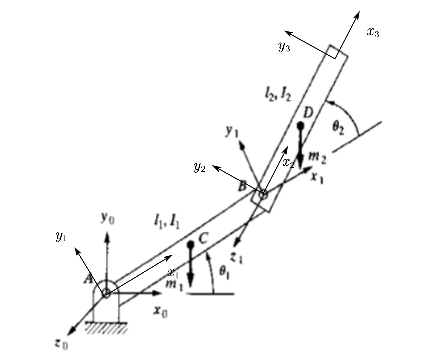
Newton-Euler 法
建立如图2的基坐标系和连杆坐标系。
两连杆质心在各自连杆坐标系中的位置矢量为:\(^1\boldsymbol{P}_C=l_1X_1\),\(^2\boldsymbol{P}_D=l_2X_2\)
由\(^CI_{XX}=\iiint_m{\left( y^2+z^2 \right) \rho \mathrm{d}}V=\frac{1}{2}m_1l_1\sin \theta _1\)
\(^CI_{YY}=\iiint_m{\left( x^2+z^2 \right) \rho \mathrm{d}}V=\frac{1}{2}m_1l_1\cos \theta _1\)
\(^CI_{ZZ}=\iiint_m{\left( x^2+y^2 \right) \rho \mathrm{d}}V=\frac{1}{2}m_1l_1\sin \theta _1+\frac{1}{2}m_1l_1\cos \theta _1\)
\(^CI_{XY}=\iiint_m{xy\rho \mathrm{d}}V=\frac{1}{3}m_1l_{1}^{3}\sin \theta _1\cos \theta _1\)
\(^CI_{XZ}=^CI_{YZ}=0\)
\(^DI_{XX}=\iiint_m{\left( y^2+z^2 \right) \rho \mathrm{d}}V=\frac{1}{2}m_2l_2\sin \theta _2\)
\(^DI_{YY}=\iiint_m{\left( x^2+z^2 \right) \rho \mathrm{d}}V=\frac{1}{2}m_1l_1\cos \theta _1\)
\(^DI_{ZZ}=\iiint_m{\left( x^2+y^2 \right) \rho \mathrm{d}}V=\frac{1}{2}m_2l_2\sin \theta _2+\frac{1}{2}m_2l_2\cos \theta _2\)
\(^DI_{XY}=\iiint_m{xy\rho \mathrm{d}}V=\frac{1}{3}m_2l_{1}^{3}\sin \theta _2\cos \theta _2\)
\(^DI_{XZ}=^DI_{YZ}=0\)
得两连杆的惯性张量:$^{C}_1=\(,\)^{D}_2=$
由于机械手是在自由空间中运动,所以它的末端受力为0,即:\(^3\boldsymbol{f}_3=0\),\(^3\boldsymbol{n}_3=0\)
由于基座是静止的,所以:\(\boldsymbol{\omega }_0=0\),\(\dot{\boldsymbol{\omega}}_0=0\)
这里考虑各连杆的重力作用,所以基座的线加速度为:\(^0\boldsymbol{v}_0=gY_0\)
相邻连杆之间的转换矩阵为: \[ { }_{i+1}^i \boldsymbol{R}=\left[\begin{array}{ccc}c_{i+1} & -s_{i+1} & 0 \\ s_{i+1} & c_{i+1} & 0 \\ 0 & 0 & 1\end{array}\right] \]
\[ { }_i^{i+1} \boldsymbol{R}=\left[\begin{array}{ccc}c_{i+1} & s_{i+1} & 0 \\ -s_{i+1} & c_{i+1} & 0 \\ 0 & 0 & 1\end{array}\right] \]
(1)外推计算各连杆的角速度、角加速度、线加速度、惯性力和惯性转矩。
连杆1的角速度、角加速度、线加速度、惯性力和惯性转矩计算如下: \[ ^1\boldsymbol{\omega }_1=_{0}^{1}\boldsymbol{R}^0\boldsymbol{\omega }_0+\dot{\boldsymbol{\theta}}_1\cdot ^1\boldsymbol{Z}_1=\left[ \begin{array}{c} 0\\ 0\\ \dot{\theta}_1\\ \end{array} \right] \]
\[ ^1\dot{\boldsymbol{\omega}}_1=_{0}^{1}\boldsymbol{R}^0\dot{\boldsymbol{\omega}}_0+_{0}^{1}\boldsymbol{R}^0\boldsymbol{\omega }_0\times \dot{\boldsymbol{\theta}}_1\cdot ^1\boldsymbol{Z}_1+\ddot{\boldsymbol{\theta}}_1\cdot ^1\boldsymbol{Z}_1=\left[ \begin{array}{c} 0\\ 0\\ \ddot{\theta}_1\\ \end{array} \right] \]
\[ ^1\dot{\boldsymbol{v}}_1=_{0}^{1}\boldsymbol{R}\left( ^0\dot{\boldsymbol{\omega}}_0\times ^0\boldsymbol{P}_1+^0\boldsymbol{\omega }_0\times \left( ^0\boldsymbol{\omega }_0\times ^0\boldsymbol{P}_1 \right) +^0\dot{\boldsymbol{v}}_0 \right) =\left[ \begin{matrix} c_1& s_1& 0\\ -s_1& c_1& 0\\ 0& 0& 1\\ \end{matrix} \right] \left[ \begin{array}{c} 0\\ g\\ 0\\ \end{array} \right] =\left[ \begin{array}{c} gs_1\\ gc_1\\ 0\\ \end{array} \right] \]
\[ \begin{aligned} ^1\dot{\boldsymbol{v}}_C&=^1\dot{\boldsymbol{\omega}}_1\times ^1\boldsymbol{P}_C+^1\boldsymbol{\omega }_1\times \left( ^1\boldsymbol{\omega }_1\times ^1\boldsymbol{P}_C \right) +^1\dot{\boldsymbol{v}}_1 \\ &=\left[ \begin{array}{c} 0\\ 0\\ \ddot{\theta}_1\\ \end{array} \right] \times \left[ \begin{array}{c} l_1\\ 0\\ 0\\ \end{array} \right] +\left[ \begin{array}{c} 0\\ 0\\ \dot{\theta}_1\\ \end{array} \right] \times \left( \left[ \begin{array}{c} 0\\ 0\\ \dot{\theta}_1\\ \end{array} \right] \times \left[ \begin{array}{c} l_1\\ 0\\ 0\\ \end{array} \right] \right) +\left[ \begin{array}{c} gs_1\\ gc_1\\ 0\\ \end{array} \right] =\left[ \begin{array}{c} gs_1-l_1\dot{\theta}_{1}^{2}\\ gc_1+l_1\ddot{\theta}_1\\ 0\\ \end{array} \right] \end{aligned} \]
\[ ^1\boldsymbol{F}_1={m_1}^1\dot{\boldsymbol{v}}_C=m_1\left[ \begin{array}{c} gs_1-l_1\dot{\theta}_{1}^{2}\\ gc_1+l_1\ddot{\theta}_1\\ 0\\ \end{array} \right] \]
\[ \begin{aligned} ^{1}\boldsymbol{N}_1&=\mathrm{ }^C{\boldsymbol{I}_1}^1\dot{\boldsymbol{\omega}}_1+^1\boldsymbol{\omega }_1\times \mathrm{ }^{C}\boldsymbol{I}_{1}^{1}\boldsymbol{\omega }_1 \\ &=\left[ \begin{matrix} \frac{1}{2}m_1l_1\sin \theta _1& -\frac{1}{3}m_1l_{1}^{3}\sin \theta _1\cos \theta _1& 0\\ -\frac{1}{3}m_1l_{1}^{3}\sin \theta _1\cos \theta _1& \frac{1}{2}m_1l_1\cos \theta _1& 0\\ 0& 0& \frac{1}{2}m_1l_1\sin \theta _1+\frac{1}{2}m_1l_1\cos \theta _1\\ \end{matrix} \right] \left[ \begin{array}{c} 0\\ 0\\ \ddot{\theta}_1\\ \end{array} \right] \\&\quad\ +\left[ \begin{array}{c} 0\\ 0\\ \dot{\theta}_1\\ \end{array} \right] \times \left[ \begin{matrix} \frac{1}{2}m_1l_1\sin \theta _1& -\frac{1}{3}m_1l_{1}^{3}\sin \theta _1\cos \theta _1& 0\\ -\frac{1}{3}m_1l_{1}^{3}\sin \theta _1\cos \theta _1& \frac{1}{2}m_1l_1\cos \theta _1& 0\\ 0& 0& \frac{1}{2}m_1l_1\sin \theta _1+\frac{1}{2}m_1l_1\cos \theta _1\\ \end{matrix} \right] \left[ \begin{array}{c} 0\\ 0\\ \dot{\theta}_1\\ \end{array} \right] \end{aligned} \]
连杆2的角速度、角加速度、线加速度、惯性力和惯性转矩计算如下: \[ ^2\boldsymbol{\omega }_2=_{1}^{2}\boldsymbol{R}^1\boldsymbol{\omega }_1+\dot{\boldsymbol{\theta}}_2\cdot ^2\boldsymbol{Z}_2=\left[ \begin{array}{c} 0\\ 0\\ \dot{\theta}_1+\dot{\theta}_2\\ \end{array} \right] \]
\[ ^2\boldsymbol{\dot\omega }_2=\left[ \begin{array}{c} 0\\ 0\\ \ddot{\theta}_1+\ddot{\theta}_2\\ \end{array} \right] \]
\[ ^2\dot{\boldsymbol{v}}_2=\left[ \begin{matrix} c_2& s_2& 0\\ -s_2& c_2& 0\\ 0& 0& 1\\ \end{matrix} \right] \left[ \begin{array}{c} gs_1-l_1\dot{\theta}_{1}^{2}\\ gc_1+l_1\ddot{\theta}_1\\ 0\\ \end{array} \right] =\left[ \begin{array}{c} gs_{12}-l_1\dot{\theta}_{1}^{2}c_2+l_1\ddot{\theta}_1s_2\\ gc_{12}+l_1\dot{\theta}_{1}^{2}s_2+l_1\ddot{\theta}_1c_2\\ 0\\ \end{array} \right] \]
\[ \begin{aligned} ^2\dot{\boldsymbol{v}}_{c2}&=\left[ \begin{array}{c} 0\\ l_2\left( \ddot{\theta}_1+\ddot{\theta}_2 \right)\\ 0\\ \end{array} \right] +\left[ \begin{array}{c} -l_2\left( \dot{\theta}_1+\dot{\theta}_2 \right) ^2\\ 0\\ 0\\ \end{array} \right] +\left[ \begin{array}{c} gs_{12}-l_1\dot{\theta}_{1}^{2}c_2+l_1\ddot{\theta}_1s_2\\ gc_{12}+l_1\dot{\theta}_{1}^{2}s_2+l_1\ddot{\theta}_1c_2\\ 0\\ \end{array} \right] \\&=\left[ \begin{array}{c} gs_{12}-l_1\dot{\theta}_{1}^{2}c_2+l_1\ddot{\theta}_1s_2-l_2\left( \dot{\theta}_1+\dot{\theta}_2 \right) ^2\\ gc_{12}+l_1\dot{\theta}_{1}^{2}s_2+l_1\ddot{\theta}_1c_2+l_2\left( \ddot{\theta}_1+\ddot{\theta}_2 \right)\\ 0\\ \end{array} \right] \end{aligned} \]
\[ ^2\boldsymbol{F}_2={m_2}^2\dot{\boldsymbol{v}}_{c2}=m_2\left[ \begin{array}{c} gs_{12}-l_1\dot{\theta}_{1}^{2}c_2+l_1\ddot{\theta}_1s_2-l_2\left( \dot{\theta}_1+\dot{\theta}_2 \right) ^2\\ gc_{12}+l_1\dot{\theta}_{1}^{2}s_2+l_1\ddot{\theta}_1c_2+l_2\left( \ddot{\theta}_1+\ddot{\theta}_2 \right)\\ 0\\ \end{array} \right] \]
\[ \begin{aligned} ^2\boldsymbol{N}_2&=\mathrm{ }^C{\boldsymbol{I}_2}^2\dot{\boldsymbol{\omega}}_2+^2\boldsymbol{\omega }_2\times \mathrm{ }^C\boldsymbol{I}_{2}^{2}\boldsymbol{\omega }_2\\ &=\left[ \begin{matrix} \frac{1}{2}m_2l_2\sin \theta _2& -\frac{1}{3}m_2l_{2}^{3}\sin \theta _2\cos \theta _2& 0\\ -\frac{1}{3}m_2l_{2}^{3}\sin \theta _2\cos \theta _2& \frac{1}{2}m_2l_2\cos \theta _2& 0\\ 0& 0& \frac{1}{2}m_2l_2\sin \theta _2+\frac{1}{2}m_2l_2\cos \theta _2\\ \end{matrix} \right] \left[ \begin{array}{c} 0\\ 0\\ \ddot{\theta}_1+\ddot{\theta}_2\\ \end{array} \right]\\ &\quad \,\,+\left[ \begin{array}{c} 0\\ 0\\ \dot{\theta}_1+\dot{\theta}_2\\ \end{array} \right] \times \left[ \begin{matrix} \frac{1}{2}m_2l_2\sin \theta _2& -\frac{1}{3}m_2l_{2}^{3}\sin \theta _2\cos \theta _2& 0\\ -\frac{1}{3}m_2l_{2}^{3}\sin \theta _2\cos \theta _2& \frac{1}{2}m_2l_2\cos \theta _2& 0\\ 0& 0& \frac{1}{2}m_2l_2\sin \theta _2+\frac{1}{2}m_2l_2\cos \theta _2\\ \end{matrix} \right] \left[ \begin{array}{c} 0\\ 0\\ \dot{\theta}_1+\dot{\theta}_2\\ \end{array} \right]\\ \end{aligned} \]
(2)内推计算各连杆所受的力和力矩。
连杆2所受的力和力矩为: \[ ^2\boldsymbol{f}_2=\mathrm{ }^2\boldsymbol{F}_2 \]
\[ \begin{aligned} \mathrm{ }^2\boldsymbol{n}_2&=\mathrm{ }^2\boldsymbol{N}_2 +\mathrm{ }^2\boldsymbol{P}_{\mathrm{D}}\times m_2\left[ \begin{array}{c} gs_{12}-l_1\dot{\theta}_1c_2+l_1\ddot{\theta}_1s_2-l_2\left( \dot{\theta}_1+\dot{\theta}_2 \right) ^2\\ gc_{12}+l_1\dot{\theta}_1s_2+l_1\ddot{\theta}_1c_2+l_2\left( \ddot{\theta}_1+\ddot{\theta}_2 \right)\\ 0\\ \end{array} \right] \\&=\mathrm{ }^2\boldsymbol{N}_2 +\left[ \begin{array}{c} 0\\ 0\\ m_2gl_2c_{12}+m_2l_1l_2s_2\dot{\theta}_{1}^{2}+m_2l_1l_2c_2\ddot{\theta}_1+m_2l_{2}^{2}\left( \ddot{\theta}_1+\ddot{\theta}_2 \right)\\ \end{array} \right] \end{aligned} \]
连杆1所受的力和力矩为: \[ \begin{aligned} ^1\boldsymbol{f}_1&=_{2}^{1}\boldsymbol{R}^2\boldsymbol{f}_2+^1\boldsymbol{F}_1 \\ &=\left[ \begin{matrix} c_2& -s_2& 0\\ s_2& c_2& 0\\ 0& 0& 1\\ \end{matrix} \right] \left[ \begin{array}{c} m_2l_1s_2\ddot{\theta}_1-m_2l_1c_2\dot{\theta}_{1}^{2}+m_2gs_{12}-m_2l_2\left( \dot{\theta}_1+\dot{\theta}_2 \right) ^2\\ m_2l_1c_2\ddot{\theta}_1-m_2l_1s_2\dot{\theta}_{1}^{2}+m_2gc_{12}+m_2l_2\left( \ddot{\theta}_1+\ddot{\theta}_2 \right)\\ 0\\ \end{array} \right] +\left[ \begin{array}{c} -m_1l_1\dot{\theta}_{1}^{2}+m_1gs_1\\ m_1l_1\ddot{\theta}_1+m_1gc_2\\ 0\\ \end{array} \right] \end{aligned} \]
\[ ^1\boldsymbol{n}_1=^1\boldsymbol{N}_1+_{2}^{1}\boldsymbol{R}^2\boldsymbol{n}_2+^2\boldsymbol{P}_{\mathrm{C}}\times ^1\boldsymbol{F}_1+^1\boldsymbol{P}_2\times _{2}^{1}\boldsymbol{R}^2\boldsymbol{f}_2 \]
(3)因为两个关节都是转动关节,提取各关节对应的 \(^i\boldsymbol{n}_i\) 向量的\(Z\)轴分量,可得两个关节的驱动力矩。
