
机器人学第七章作业
机器人学第七章作业
一个单连杆转动关节机器人初始位置的关节角 \(\theta=-5^\circ\),希望在 4s 内平滑地将关节转动到 \(\theta=80^\circ\)的位置。求:
完成此运动并且机器人停在目标位置的三次曲线方程,编程绘制关节的位置、速度和加速度随时间变化的函数;
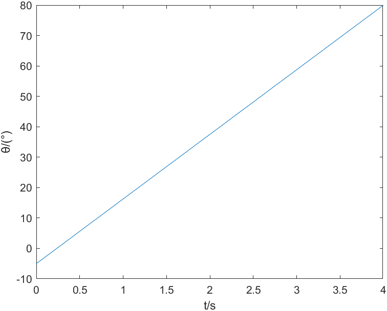
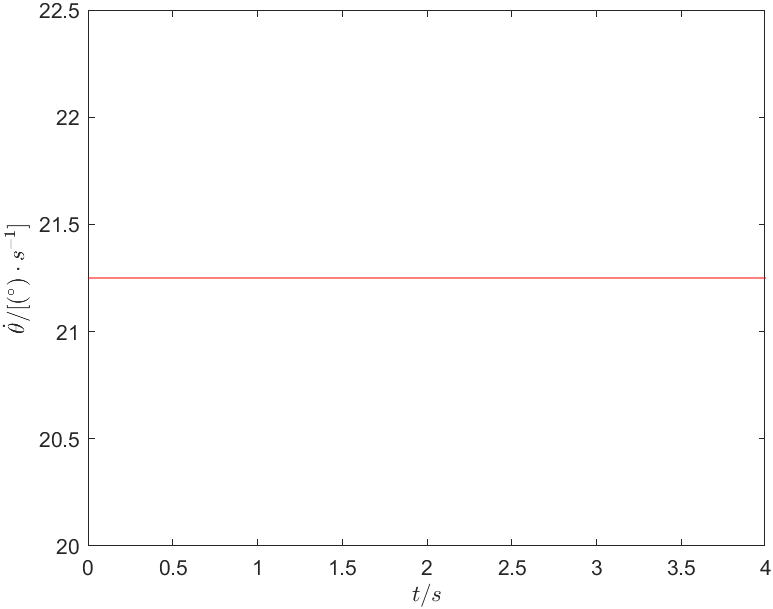
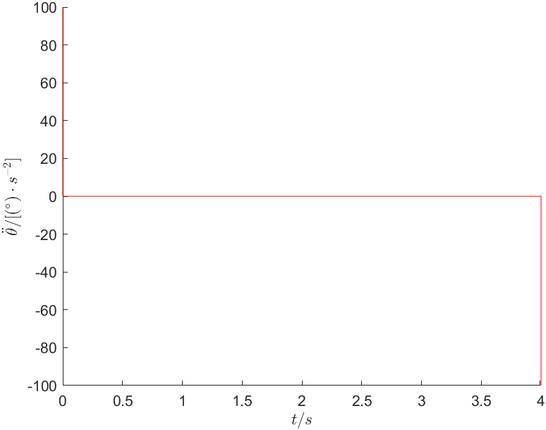
解:由题知,角度约束: \[ \begin{cases} \theta \left( 0 \right) =-5^\circ\\ \theta \left( t_f \right) =80^\circ\\ \end{cases} \] 因为平滑转动,速度约束: \[ \dot{\theta}\left( 0 \right) =\dot{\theta}\left( t_f \right) =21.25 \] 由三次多项式的系数求解公式\(\left\{\begin{array}{l}a_0=\theta_0 \\ a_1=\dot{\theta}_0 \\ a_2=\frac{3}{t_f^2}\left(\theta_f-\theta_0\right)-\frac{2}{t_f} \dot{\theta}_0-\frac{1}{t_f} \dot{\theta}_f \\ a_3=-\frac{2}{t_f^3}\left(\theta_f-\theta_0\right)+\frac{1}{t_f^2}\left(\dot{\theta}_0+\dot{\theta}_f\right)\end{array}\right.\),求解可得各系数为: \[ \begin{cases} a_0=-5\\ a_1=21.25\\ a_2=0\\ a_3=0\\ \end{cases} \] 所以该机器人的三次多项式轨迹函数为: \[ \theta \left( t \right) =-5+21.25t \] 4s内关节的角度变化如图1所示。关节的角速度和角加速度的变化分别如图2和图3所示。
完成此运动并且机器人停在目标位置的带有抛物线拟合的直线轨迹曲线方程,编程绘制关节的位置、速度和加速度随时间变化的函数。
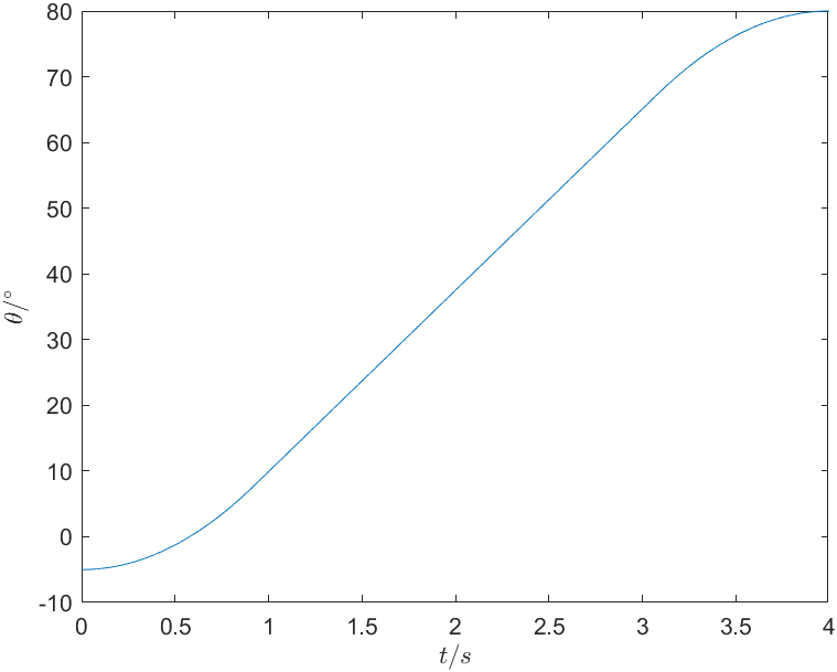
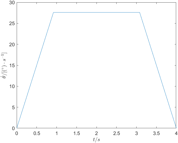
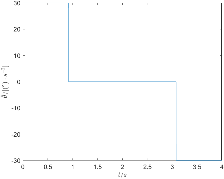
解:首先选取过度域的加速度 \(\ddot\theta\) ,其应满足: \[ \ddot{\theta}\geqslant \frac{4\left( \theta _f-\theta _0 \right)}{t^2}=\frac{340^\circ}{16\mathrm{s}}=21.25^\circ/\mathrm{s} \] 选取 \(\ddot\theta=30^\circ\) ,求得 \(t_b=0.9199\mathrm{s}\) ,可得关节的轨迹函数为: \[ \theta \left( t \right) =\begin{cases} -5+15t^2& 0\leqslant t<0.9199\\ -17.69324+27.597t& 0.9199\leqslant t\leqslant 3.0801\\ -15t^2+120t-160& 3.0801<t\leqslant 4\\ \end{cases} \] 4s内关节的角度变化如图4所示。关节的角速度和角加速度的变化分别如图5和图6所示。
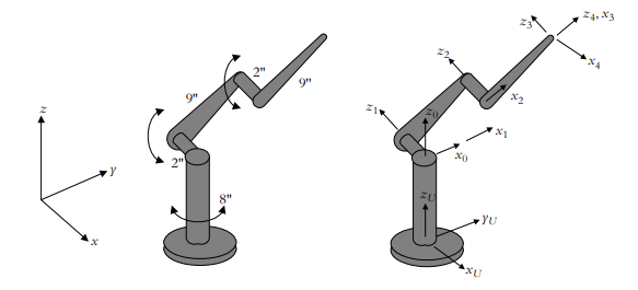
加利福尼亚理工学院3自由度机器人如图所示,基座高8,杆长9,关节长2;已知该机器人逆运动学方程:
\[ \begin{aligned} &\theta_1=\arctan \left(-P_x / P_y\right) \\ &\theta_3=\arccos \left[\left(\left(P_y / C_1\right)^2+\left(P_z\right)^2-162\right) / 162\right] \\ &\theta_2=\arccos \left[\left(P_z C_1\left(1+C_3\right)+P_y S_3\right) /\left(18\left(1+C_3\right) C_1\right)\right] \end{aligned} \]
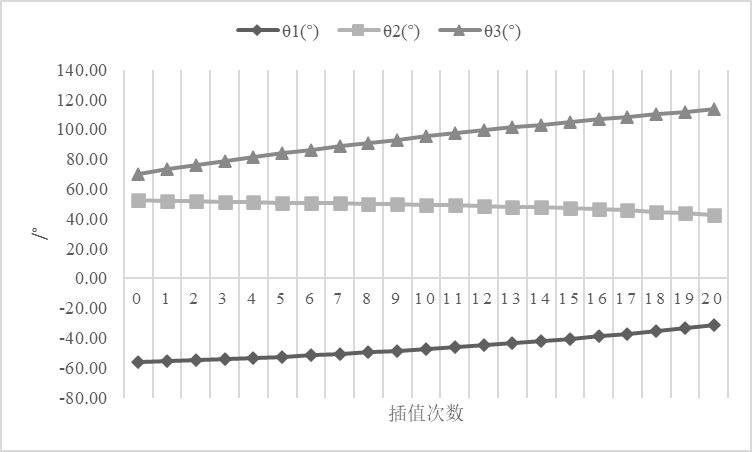
期望末端从点 $(9,6,10) $沿直线移动到点 \((3,5,8)\),求3个关节在路径20等分各点的角度值;绘制3个关节运动曲线;
解:由题知插值点数 \(n=20\) ;
机器人参数设置如下:插补时间:\(0.02\mathrm{s}\)。
计算可得两节点之间的直线距离为 \(l=\sqrt{41}\mathrm{mm}\) ,步长 \(\varDelta =0.35\mathrm{mm/s}\) ,末端速度 \(v=17.5\mathrm{mm/s}\) ,总运动时间 \(t=0.365714\mathrm{s}\) 。
由逆运动方程解得表1,3个关节运动曲线如图8所示。
| 次数 | \(P_x(\mathrm{mm})\) | \(P_y(\mathrm{mm})\) | \(P_z(\mathrm{mm})\) | \(\theta_1(\mathrm{rad^{-1}})\) | \(\theta_2(\mathrm{rad^{-1}})\) | \(\theta_3(\mathrm{rad^{-1}})\) | \(\theta_1(^\circ)\) | \(\theta_2(^\circ)\) | \(\theta_3(^\circ)\) |
|---|---|---|---|---|---|---|---|---|---|
| 0 | 9 | 6 | 10 | -0.98 | 0.91 | 1.22 | -56.31 | 52.32 | 70.15 |
| 1 | 8.7 | 5.95 | 9.9 | -0.97 | 0.91 | 1.28 | -55.63 | 51.98 | 73.10 |
| 2 | 8.4 | 5.9 | 9.8 | -0.96 | 0.90 | 1.33 | -54.92 | 51.66 | 75.92 |
| 3 | 8.1 | 5.85 | 9.7 | -0.95 | 0.90 | 1.37 | -54.16 | 51.37 | 78.64 |
| 4 | 7.8 | 5.8 | 9.6 | -0.93 | 0.89 | 1.42 | -53.37 | 51.09 | 81.25 |
| 5 | 7.5 | 5.75 | 9.5 | -0.92 | 0.89 | 1.46 | -52.52 | 50.82 | 83.78 |
| 6 | 7.2 | 5.7 | 9.4 | -0.90 | 0.88 | 1.50 | -51.63 | 50.54 | 86.22 |
| 7 | 6.9 | 5.65 | 9.3 | -0.88 | 0.88 | 1.55 | -50.69 | 50.27 | 88.58 |
| 8 | 6.6 | 5.6 | 9.2 | -0.87 | 0.87 | 1.59 | -49.69 | 49.98 | 90.86 |
| 9 | 6.3 | 5.55 | 9.1 | -0.85 | 0.87 | 1.62 | -48.62 | 49.68 | 93.08 |
| 10 | 6 | 5.5 | 9 | -0.83 | 0.86 | 1.66 | -47.49 | 49.35 | 95.22 |
| 11 | 5.7 | 5.45 | 8.9 | -0.81 | 0.85 | 1.70 | -46.28 | 48.99 | 97.30 |
| 12 | 5.4 | 5.4 | 8.8 | -0.79 | 0.85 | 1.73 | -45.00 | 48.59 | 99.32 |
| 13 | 5.1 | 5.35 | 8.7 | -0.76 | 0.84 | 1.77 | -43.63 | 48.14 | 101.28 |
| 14 | 4.8 | 5.3 | 8.6 | -0.74 | 0.83 | 1.80 | -42.17 | 47.63 | 103.17 |
| 15 | 4.5 | 5.25 | 8.5 | -0.71 | 0.82 | 1.83 | -40.60 | 47.05 | 105.00 |
| 16 | 4.2 | 5.2 | 8.4 | -0.68 | 0.81 | 1.86 | -38.93 | 46.39 | 106.78 |
| 17 | 3.9 | 5.15 | 8.3 | -0.65 | 0.80 | 1.89 | -37.14 | 45.64 | 108.49 |
| 18 | 3.6 | 5.1 | 8.2 | -0.61 | 0.78 | 1.92 | -35.22 | 44.79 | 110.14 |
| 19 | 3.3 | 5.05 | 8.1 | -0.58 | 0.76 | 1.95 | -33.16 | 43.82 | 111.74 |
| 20 | 3 | 5 | 8 | -0.54 | 0.75 | 1.98 | -30.96 | 42.73 | 113.27 |
根据2.1求得的三个关节角度始末位置,运用三次多项式对每个关节进行轨迹规划,运行时间假设均为10s。根据关节轨迹规划结果绘制末端点的运动曲线;
解:
对关节1分析:
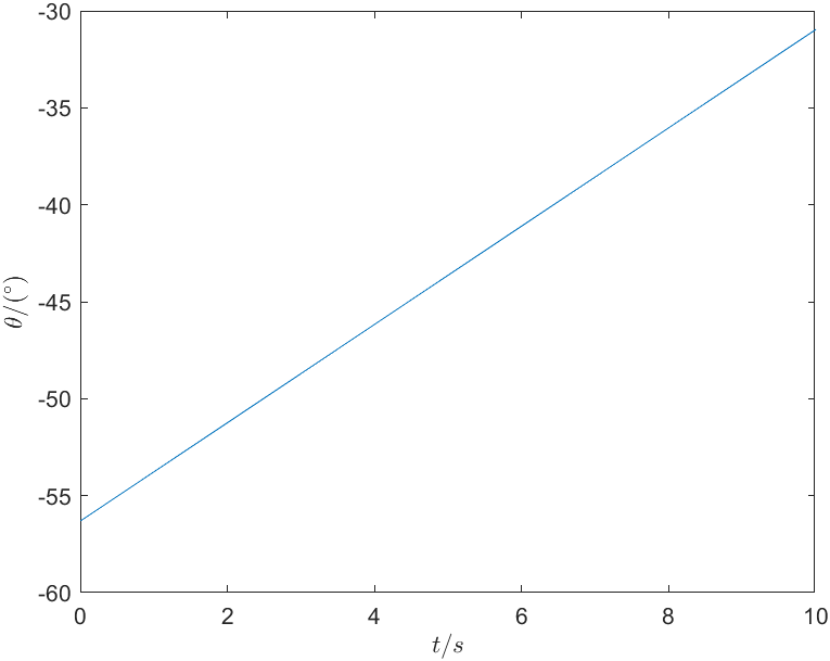
角度约束: \[ \begin{cases} \theta \left( 0 \right) =-56.31^\circ\\ \theta \left( t_f \right) =-30.96^\circ\\ \end{cases} \] 假设平滑转动,速度约束: \[ \dot{\theta}\left( 0 \right) =\dot{\theta}\left( t_f \right) =2.535 \] 由三次多项式的系数求解公式\(\left\{\begin{array}{l}a_0=\theta_0 \\ a_1=\dot{\theta}_0 \\ a_2=\frac{3}{t_f^2}\left(\theta_f-\theta_0\right)-\frac{2}{t_f} \dot{\theta}_0-\frac{1}{t_f} \dot{\theta}_f \\ a_3=-\frac{2}{t_f^3}\left(\theta_f-\theta_0\right)+\frac{1}{t_f^2}\left(\dot{\theta}_0+\dot{\theta}_f\right)\end{array}\right.\),求解可得各系数为: \[ \begin{cases} a_0=-56.31\\ a_1=2.535\\ a_2=0\\ a_3=0\\ \end{cases} \] 所以该机器人的三次多项式轨迹函数为: \[ \theta_1 \left( t \right) =-56.31+2.535t \] 可得关节1的运动曲线如图9所示。
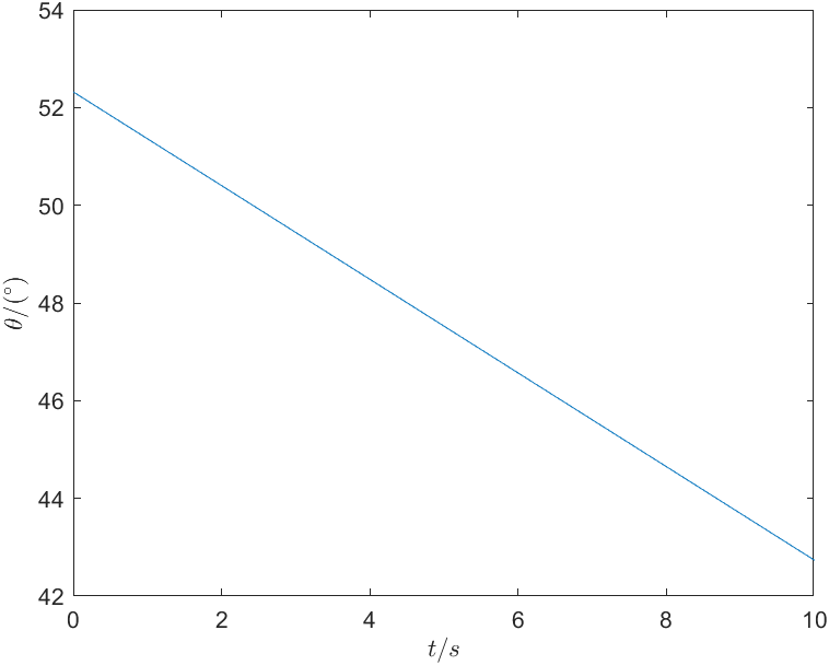
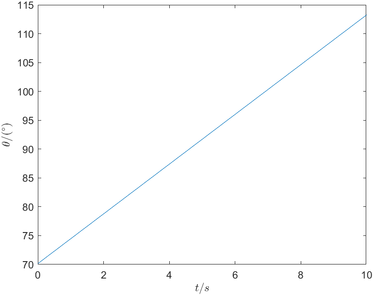
同理可得关节2和关节3的运动曲线,分别如图10与图11所示。 \[
\theta_2 \left( t \right) =52.32-0.959t\\
\theta_3 \left( t \right) =70.15+4.312t
\]
对比上述两种规划的过程和结果,说明各自的优缺点。
方法一的机器人的运动轨迹是直观的,容易理解和描述,但插补运算量大,计算复杂,且所得的轨迹不一定光滑,“拐点”较多且明显。
方法二的轨迹光滑,但约束条件不足,所得的轨迹不一定精确。
